Posts

Showing posts from February, 2014

Induction Motors Duty Cycles

Type of Duty The following shall be the duty types: Sl -Continuous duty The motor works at a constant load for enough time to reach temperature equilibrium. S2 -Short time duty The motor works at a constant load, but not long enough to reach temperature equilibrium. The rest periods are long enough for the motor to reach ambient temperature S3 -Intermittent periodic duty Sequential, identical run and rest cycles with constant load. Temperature equilibrium is never reached. Starting current has little effect on temperature rise S4 -Intermittent periodic duty with starting Sequential, identical start, run and rest cycles with constant load. Temperature equilibrium is not reached, but starting current affects temperature rise. S5 -Intermittent periodic duty with starting and electric braking Sequential, identical cycles of starting, running at constant load and running with no load. No rest periods. S6 -Continuous duty with intermittent periodic loading Sequential, identical cycles of run

American Wire Gauge; AWG calculations

Image
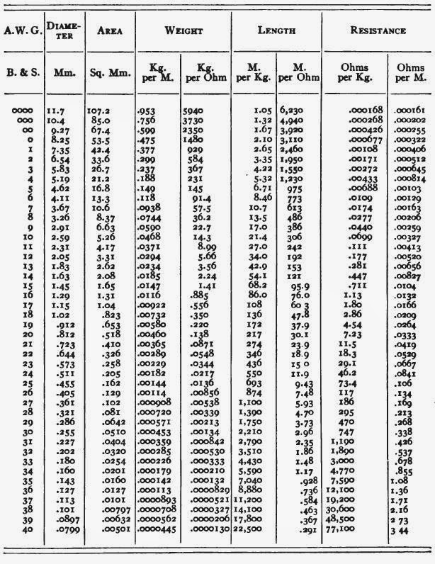
AMERICAN WIRE GAUGE By definition, No. 36 AWG is 0.0050 inches in diameter,  and No. 0000 is 0.4600 inches in diameter.  The ratio of these diameters is 92,  and there are 40 gauge sizes from No. 36 to No. 0000, or 39 steps. Using this common ratio, wire gauge sizes vary according to the following formula:  The diameter of a No.  n  AWG wire is  the gauge can be calculated from the diameter using and the cross-section area is . Sizes with multiple zeros are successively larger than No. 0 and can be denoted using " number of zeros /0", for example 4/0 for 0000. For an m /0 AWG wire, use n = −( m −1) = 1− m in the above formulas. For instance, for No. 0000 or 4/0, use n = −3. The ASTM B 258-02 standard defines the ratio between successive sizes to be the 39th root of 92, or approximately 1.1229322. ASTM B 258-02 also dictates that wire diameters should be tabulated with no more than 4 significant figures, with a resolution of no more than 0.0001 inches (0.1 mils) for wires la

Full Load Speed of Induction Motor

Slip  and Full-load speed of Motor The speed at which rated full-load torque is delivered at rated power output is full-load speed. It is generally given as "RPM" on the nameplate. This speed is sometimes called "slip" speed or actual rotor speed rather than synchronous speed. Synchronous speed is the speed at which the motor would run if it were fixed to the ac power line frequency; that is, if it turned at the same speed as the rotating magnetic field created by the combination of winding pattern and power line frequency. An induction motor's speed is always less than synchronous speed and it drops off as load increases. For example, for 1800 rpm synchronous speed, an induction motor might have a full-load speed of 1748 rpm, this drop in RPM is due to slip of an induction motor. Slip speed is difference between synchronous speed and actual rotor speed. In induction motors Slip is directly proportional to torque of motor, so greater will be the slip greater wil

Lighting System Designing Zones

There are following lighting Zones in Designing lighting system of any area:- Zone Recommended Uses or Areas Zoning Considerations LZ-0 Lighting Zone 0 should be applied to areas in which permanent lighting is not expected and when used, is limited in the amount of lighting and the period of operation. LZ-0 typically includes undeveloped areas of open spaces, Parks , Outside area of any industry . Special review should be required for any permanent lighting in this zone. LZ-1 Lighting Zone 1 pertains to areas that desire low lighting levels. These typically residential communities with low Population, rural town centers, business parks, and other commercial or industrial/storage areas typically with limited night time activity. This zone also Includes agricultural zone districts; rural residential zone districts; business parks; open space include preserves in developed areas. LZ-2 Lighting Zone 2 pertains to areas with moderate lighting levels. These typically include Highly Populated

Tube lights and its sizes; Tube light diameters

Tube lights are part of every industry and household. LED tube-lights are also coming in same sizes that of traditional lights. Diameter of tube-light is described in 1/8 of the inch. So a T8 tube light is 1 inch diameter tube-light. This is obtained by simply multiplying 1/8 by numeric letter of description of tube light.   Sizes of tube lights vary from T2 to T17. Electronic ballasts, and T5 or T16 ( 5 / 8 " Ø or 15.875 mm Ø) for very small lamps which may even operate from a battery powered device. Fluorescent tube diameter designation comparison Tube diameter designations Tube diameter measurements Extra Imperial-based Metric-based Inches Ø  (") Millimeters Ø  (mm) Socket Notes T4 N/A 4 / 8 " Ø 12 mm Ø G5 Bipin Slim lamps, tube lengths may vary T5 T16 5 / 8 " Ø 15.875 mm Ø G5 Supersedes T8, introduced in the 1990s T8 T26 8 / 8 "

Fluorescent Lamp and Bulbs nomenclature

Image
Fluorescent Lamp Labeling For Tube lights:- There is certain nomenclature which is used while labelling tube lights. The actual fluorescent tubes are identified by several letters and numbers and will look something like  'F40CW-T12' or 'FC12-T10'. So, the typical labeling is of the form FSWWCCC-TDD (variations on this format are possible): ·  F - Fluorescent lamp.  G means Germicidal shortwave UV lamp. ·  S - Style - no letter indicates normal straight tube; C for Circline. ·  WW - Nominal power in Watts. 4, 5, 8, 12, 15, 20, 30, 40, etc. ·  CCC - Color.  W=White, CW=Cool white,  WW=Warm white,  BL/BLB=Black light, etc. ·  T - Tubular bulb. ·  DD - Diameter of tube in of eighths of an inch. T8 is 1", T12 is 1.5", etc. For the most common T12 (1.5 inch) tube, the wattage (except for newer energy saving types) is usually 5/6 of the length in inches. Thus, an F40-T12 tube is 48 inches long. For Tungsten lamps:- There are lamps (bulbs and LED who are available i

Fluorescent Lamp Basics

Fluorescent Lamp Basics The fluorescent lamp was the first major advance to be a commercial success in small scale lighting since the tungsten incandescent bulb. Its greatly increased efficiency resulted in cool (temperature wise) brightly lit workplaces (offices and factories) as well as home kitchens and baths. The development of the mercury vapor high intensity discharge (HID) lamp actually predates the fluorescent (the latter being introduced commercially in 1938, four years after the HID). However, HID type lamps have only relatively recently become popular in small sizes for task lighting in the home and office; yard and security area lighting; and light source applications in overhead, computer, and video projectors. Fluorescent lamps are a type of gas discharge tube similar to neon signs and mercury or sodium vapor street or yard lights. A pair of electrodes, one at each end - are sealed along with a drop of mercury and some inert gases (usually argon) at very low pressure insi

Air Gap Values while designing Machine

Air gap is a necessary evil. Which means you can't avoid air gap in motors as if there is no air gap motor will not start. So you can't avoid air gap instead air gap can be minimized to as low value as possible. In electrical systems air gap is main cause of concern in designing electrical motors. In an electromagnetic devices there is uniform practice that material selected is such that it will offer low resistance to passage of magnetic flux. This will reduces the electrical energy demand for creating the required flux. But there is always air gap in rotating machines which is unavoidable.  This air gap requires increase in magnetizing current as there is high resistance of air gap which will requires more electrical energy to generate required flux. This air gap will leads to undesirable electrical losses. There is rule of thumb that  higher the motor speed, the larger the gap.  Why Air Gap Should be Small? Let's State by taking an example of an Induction motor when Powe

Precautions while working with Gas Discharge Lamps & Fixtures

                Safely Working with Gas Discharge Lamps and Fixtures Fixtures for gas discharge lamps may use up to 30,000 V while starting depending on technology. And, they are often not isolated from the power line. Neon signs are powered by transformers or electronic ballasts producing up to 15,000 V or more. Thus, the only safe way to work with these is to assume that they are potentially lethal and treat them with respect. Hazards include: Electric shock. There is usually little need to probe a live fixture. Most problems can be identified by inspection or with an ohmmeter or continuity tester when unplugged. Discharge lamps and fixtures using iron ballasts are basically pretty inert when unplugged. Even if there are small capacitors inside the ballast(s) or for RFI prevention, these are not likely to bite. However, you do have to remember to unplug them before touching anything! Neon signs using iron transformers are also inert when unpowered -

Gas Discharge lamps Basics

                                                    Gas discharge lamp basics The use of electrically excited gas discharges significantly predates the invention of the incandescent lamp. Physics labs of yesteryear as well as today have use of a variety of gas filled tubes used for numerous purposes involving light generation including spectroscopy, materials analysis, studies of gas dynamics, and laser pumping. Look through any scientific supply catalog and you will see many different types of gas filled tubes in all shapes and sizes. Gas discharge lamps are used in virtually all areas of modern lighting technology including common fluorescent lighting for home and office - and LCD backlights for laptop computers, high intensity discharge lamps for very efficient area lighting, neon and other miniature indicator lamps, germicidal and tanning lamps, neon signs, photographic electronic flashes and strobes, arc lamps for industry and A/V projectors, and many more. Gas discharge automotiv