Posts

Showing posts from April, 2014

Why one pin of Plug top is Larger in length and diameter from other pins?

Image
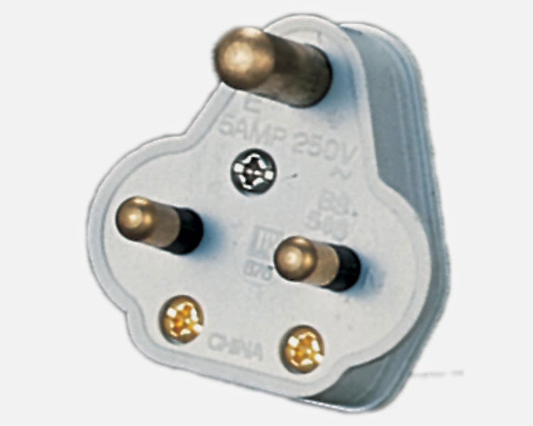
We have often seen in our routine that 3rd pin of plug top has larger length and diameter then other pins there is technical reasons behind the see below we will clear the same. This is due to following reason:- Resistance = Resistivity X Length                           Area larger will the area of earthing contact lower will be the resistance. You can see from the image below that earth pin has larger area then other pins. There are following reasons which we will derive from the larger 3rd pin are:- 1. It will provide protection to both human being and appliance by ensuring that 1st earth get connected before any appliance get supply and during disconnection of appliance earth will remains connected until supply get disconnected. 2. Due to larger area of earthing pin resistance get lower which will divert all fault current to earth quickly before it get passed to other system and may cause any shock.

Current Transformer Applications and their connections

Image
Current transformers are used for measurement of current in any circuit. It has same working principle of that transformer but only used for step down of current.  Current Transformer are used in measurement circuits , it is advisable to use CT instead of connection ammeter in the circuit as currents above 20A ammeter size becomes so large which is not feasible that is why current transformers are used.  Current transformer  primary has only one turn. Current transformer primary is not really a turn but just a conductor. The primary winding of Current Transformer has very few turns, while the secondary winding have a many turns depends upon how much the current must be stepped down. There is extra precaution required during connections of CT are that secondary of CT should never be kept open which otherwise leads to very high secondary voltages which ultimately leads to burning of CT or even explosion of CT. So such conditions should be avoided. Now let’s discuss about the same by con

Air conditioner Power Consumption

Whenever anyone going to Install an AC then first everyone planned power charges that they will have to pay after using AC. Actually it is correct that one ton of air-conditioning is equal to 12,000 btu/hr. However the other question trying to convert a one ton A/C unit into kw/hr consumed is very dependant on the make and model of the air-conditioner, as well as its EER (energy Efficiency Rate). These range from 6-14 EER. Standard average one ton A/C unit consumes 1.335 KW/hr.  #13650 btu= 4.0004205 kwh  According to that for 1 Ton Ac 12000=3.51685 kwh  And , for 2 Ton AC 24000 btu required , for 2 ton Ac ,  as per calculation 7.33706 kwh power required.  But in practical is not there.  As 2 Ton AC is taking max 14 to 15 Amp.Load.  KW= VI  = 15*220  =3.3 kwh So for 1 Ton AC Power Consumption stands at 1.7 KWH For 1.5 Ton AC Power consumption stands at 2.5 KWH Similarly for 2 Ton AC Power consumption will be 3.3 KWH.

66KV to 132KV Cables Tests requirement

Image
Following tests as Shown in figure must be done for 66KV & 132KV Cables as per IS: 60840 and IS:7098 part 3. You May visit at link for difference between XPLE and PVC Cables:- http://electrialstandards.blogspot.in/2014/03/difference-between-xlpe-and-pvc-cables.html Also find out advantages of XLPE cables over Oil filled Paper Insulated cables:- http://electricalsystembasics.com/2014/04/xlpe-cables-advantages-oil-filled-paper-insulated-cables.html As per IS Standards 7098 Part 3 :- Cross-Linked Polyethylene Insulated Thermoplastic Sheathed Cables - Specification. Part -3 for working voltages from 66 Kv up to and including 220 kV.

is Copper as earth pit is better then GI earth pit?

It has been often found that most of think that material used for earthing will reduce earthing resistance. It has been often misconception that copper earthing plate or rod will have lower earth pit resistance then GI earthing plate or rod. Lets clear this fundamental regarding as often falling in this trap will lead to higher investment on earthing by using copper as earthing material. If one considers a plate electrode, the approximate resistance to earth is: Resistance formula for Pipe earthing (R) = (100r/2Ï€L) X loge (4L/d) ·           L= Length of Pipe/Rod in cm d=Diameter of Pipe/Rod in cm r = Resistivity of Soil Ohm-meter. Resistance formula for Plate earthing (R) = (r/A) X   under root(Ï€/A). ·          r = Resistivity of Soil Ohm-meter. ·          A=Area of Earthing Plate m3. As can be seen from the above  formulas , only the resistivity of the soil and the physical dimensions of the electrode play a major role in determining the electrode resistance to earth. The m

Difference between grounding and earthing

There is always misconception related to difference between grounding and Earthing. Lets discuss the same:- It’s generally Myth about ‘Grounding’ is that grounding done for current carrying parts to ground like transformer or generator neutral and ‘Earthing’ means connection of non-current carrying parts to ground, like metallic enclosures. But as per IS 3043-1987  the terms ‘earthing’ and ‘grounding’ are synonymous.  Possibly the various nomenclature is because of the usual conflicting using British language between your People in America & the British.  As the British called it as being ‘earthing’, the People in America called it as being ‘grounding’.  IEC & IS Standards refer as ‘earthing’, while IEEE & ANSI Standards refer as ‘grounding’. To quote from IEC 60050: “The terms ‘earth’ in addition to ‘ground’ have both been generally use to explain the most popular energy/signal reference interchangeably all over the world in the Electro-technical terminology. As the USA

Fault current direction

There are very misconceptions about the direction of fault current. Usually it has been misinterpreted that as from source to load as everyone thinks that’s source will supply load current and voltage. Fault current always flows backwards i.e. if fault occurred at Motor then first it's O/L get tripped not directly causing Transformer tripping. Although current is drawn from Source but fault current always from Fault end to backward, as during fault at load heavy current will flows at load end as during fault load resistance reduced to very low value . That is how Electrical system is designed for load fault current. Electrical system should be designed in Such a way that protection equipment connected for protection of load much immediately isolate load from source. e.g. if load rated current is 300A then load end MCCB/SFU must be of 400A with fault current rating depending upon Transformer rating and impedance. Now Load end MCCB is of 400A and protection equipment such be set at 3

Star Delta Starter Changing Direction of motor

Image
Star Delta Starter connected motor direction can be changed by changing either connections at main input line connections and O/P connections at Main and Delta contactors. Star-Delta Starter Connection changing circuit is shown above.

Induction motors not kept running in Star Connections

Induction motors are not kept on running in Star connections due to following reasons:- In Star connections, Phase current= Line current and Phase voltage= Line voltage/  √3. As Power = √3X Line Voltage XLine Current X Power Factor This means that during starting voltage get reduced by factor 1/√3. So current is also get reduced by factor 1/√3. So Torque also gets reduced by factor 1/3 as Torque is directly proportional to square of voltage. Due to reduced voltage Motor unable to take-up higher loads. So motor power get reduced by 1/3 times then in Delta connections that is why motor is not kept running in Star connections. As motor is get under utilized. So Motor will kept on running at reduced power and means motor will run at low efficiency

Star Delta Starter and applications

Image
Motors up-to 7.5 KW are started using direct online starters but above 7.5 KW induction motors are started using Star-Delta Starters as if motors above 7.5 KW are started directly then there will be voltage disturbances in line due to large starting current surges. So let’s discuss how this Star-Delta Starter works. Working Principal of Star-Delta Starter: First of all you must know what Star and Delta connections are:- Star Connection or Wye Connections:- In Star connections,  Phase current= Line current and Phase voltage= Line voltage/  √3. This means that during starting voltage get reduced by factor 1/√3. So Torque also gets reduced by factor 1/3 as Torque is directly proportional to square of voltage. Current also get reduced by 1/ √3 in  induction motor if motor is Started in Star connections. If You want to know about Direct online starter first then click link here Delta Connections:- In Delta connections Phase Voltage = Line Voltage and  Phase current=  Line Current /  √3. Aft

Direct online Applications Reverse Forward, Limit & Level Switch, Remote Starters

Image
Earlier we discussed about Direct Online Starter Basic Circuit. For Basic Circuit diagram of Direct online visit at link below:- http://electrialstandards.blogspot.in/2014/04/direct-online-dol-starter.html Now let’s discuss about Direct online Starters following circuits:- 1 .        Reverse forward direct online Starter. 2.        Limit Switch & level Switch circuit in DOL. 3.        Remote Start/Stop Direct online Starter Circuit. Let’s discuss their  circuitry  one by one:- 1.       Reverse Forward Direct Online Starter:- Power and control circuit for Reverse forward Direct online starter is as below:- In control circuit C1 contactor is used as forward contactor and C2 contactor is used as Reverse contactor And also Reverse contactor NC is used in series with Forward contactor starting and also forward contactor NC is used in circuit of Reverse contactor so that while motor is operating in one direction it’s other direction contactor could not hold, Which otherwise leads to Shor

Direct Online (DOL) Starter

Image
Different Starting methods are used for starting motors depending upon the rating of motor. Direct online starter is simplest starter used for starting of Induction motors and in short it is also known as DOL starter. Direct online starters are used only for motors upto 7.5 KW as they draw heavy inrush current during starting of motor. In these starters full voltage is comes across motor and draws 6-8 times rated current at starting of motor. Due to heavy current drawn during starting of motor these starters are used only for motors upto 7.5 KW rating only. Main Parts of Direct online starter:- Direct online Starter consists of following parts:- 1.        Electromagnetic Contactor 2.        Overload relay 3.        Main MCB 4.        ON/OFF switches All Starters has two circuit diagrams :- 1.        Power circuit Diagram 2.        Control circuit diagram Let’s discuss one be one:- 1.       Power circuit diagram:- Power circuit is usually also called three phase diagram. In That diagra

Battery Rating Calculation

Image
Batteries are usually connected in Series as in Series Voltage get added up and current remains the same. BATTERY RATING CALCULATION The formula employed rating calculation is as stipulated below:- FORMULA EMPLOYED:                                                 Capacity of Battery (AH) = (DC Current X Duration in Hrs)/( %age capacity utilization) Where, DC Current = (UPS (KVA) x 1000 x Load Power Factor (=1))/( Inverter efficiency x End Voltage)  Hence, VAH = AH x Nominal Voltage  For e.g.: for 3 KVA UPS, 1 hour Backup having 18 no. batteries: DC Current = (5 x 1000 x 1)/ (0.95 x 10.5 x 18) =27.85A Battery “AH” =   (27.85 x 1.0)/ (0.62) = 44.91 Hence , 18 no.s of 12V/42AH batteries will suffice . TOTAL VAH = 18 x 12 x 42 = 9072 VAH The following assumptions have been made in the above calculations:- 1. DC Voltage – 216 for 5 KVA 2. End cell voltage / battery of 10.5 V 3. Load Power Factor = 1.0 4. Inverter efficiency = 95% % Capacity utilization is:  Duration % Capacity utilization ½

Three phase Motor Insulation classes

Maximum allowable temperatures of various types of insulation Insulation Class Maximum Permissible temperature in Degree Celsius Y 90 A 120 B 130 F 155 H 180 C ABOVE 180 Insulation classes types are explained in details as below:- 1.         Class-Y insulation: These type on insulations can Withstands a temperature of up to 90°C these type of insulations are made of Cotton, silk, or paper. 2.        Class-A insulation: These type of insulations can Withstands a temperature of up to 105°C, these type of insulations are made from reinforced Class-Y materials with impregnated varnish or insulation oil. Insulation consists of materials such as cotton, silk, and paper when suitably impregnation or coated or when immersed in dielectric oil. 3.        Class-E insulation: These types of insulation materials can Withstands a temperature of up to 120°C . 4.        Class-B insulation: These type of insulations can Withstands a temperature of up to 130°